IRF840 Description
The IRF840, featuring the advanced PowerMESH™ II technology, represents a significant evolution in MOSFET design, building upon the foundations of the first-generation MESH OVERLAY™. This enhancement in layout and structure greatly improves the Ron*area figure of merit, getting lower on-resistance for more efficient power conversion.
IRF840 Pinout

G (Gate): This is the control pin that receives the input signal to turn the MOSFET on or off. A voltage applied to the gate modulates the conductivity between the drain and source.
D (Drain): This is the output pin where the load is connected. The drain is the terminal where current flows out of the MOSFET when it is turned on.
S (Source): This is the terminal where current enters the MOSFET. The source is typically connected to ground in most circuits
IRF840 Symbol

IRF840 Footprint

IRF840 3D Model

IRF840 Circuit


IRF840 Specification
| Features | Specification |
| Drain-Source Voltage (Vdss) | 500V |
| Continuous Drain Current (Id) | 8A |
| Drive Voltage (Max Rds On, Min Rds On) | 10V |
| Pulsed Drain Current (Id) | 32A |
| Gate-Source Voltage (Vgs) | ±20V |
| Rds(on) | 0.85Ω (Max) |
| Rds On (Max) @ Id, Vgs | 850mOhm @ 4.8A, 10V |
| Total Gate Charge (Qg) | 94nC |
| Vgs(th) (Max) @ Id | 4V @ 250µA |
| Gate Charge (Qg) (Max) @ Vgs | 63 nC @ 10 V |
| Rise Time (tr) | 35ns |
| Fall Time (tf) | 29ns |
| Input Capacitance (Ciss) (Max) @ Vds | 1300 pF @ 25 V |
| Power Dissipation (Pd) | 125W |
| Operating Junction Temperature (Tj) | -55°C - 150°C |
| Thermal Resistance, Junction-to-Case (RthJC) | 1.0°C/W |
| Package | TO-220-3 |
IRF840 Features
Typical RDS(on) = 0.75 Ω
Dynamic dV/dt rating
Extremely high dv/dt capability
100% AVALANCHE TESTED
New high voltage benchmark
Gate charge minimized
Fast switching
Ease of paralleling
Simple driving requirements
IRF840 Applications
High current, High speed switching
Switch mode power supplies (SMPS)
DC-AC converters for welding equipment and uninterruptible power supplies and motor drives
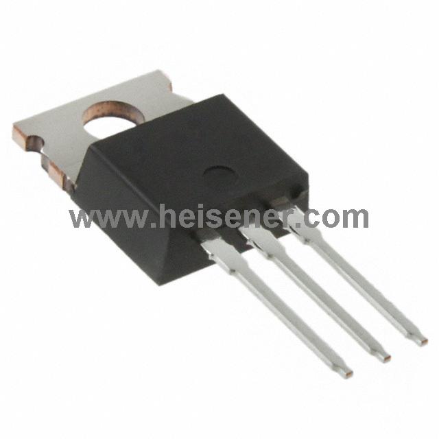
IRF840 Package
The IRF840 MOSFET is housed in a TO-220-3 package, which features three leads: the gate (G), drain (D), and source (S), with the metal tab connected to the drain, allowing for efficient heat dissipation when mounted to a heatsink. This package is designed to handle significant power dissipation, making the IRF840 suitable for applications such as power supplies, motor controls, and high-speed switching circuits.

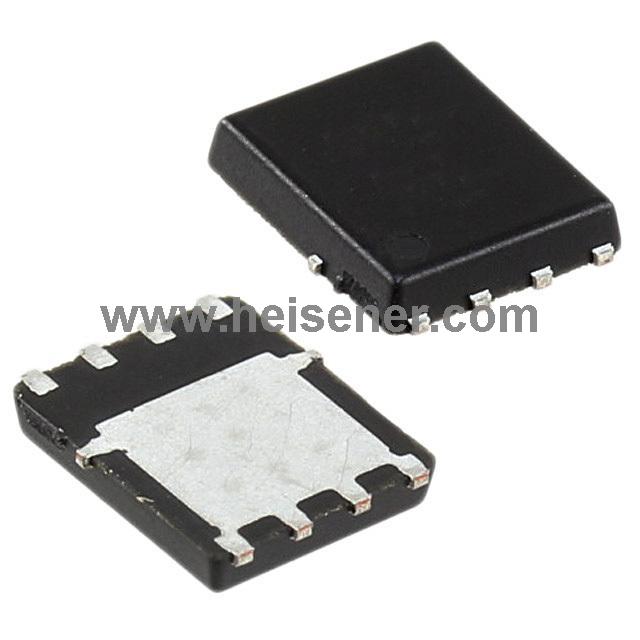
IRF840 Alternatives
When selecting alternatives to the IRF840, you can consider several common N-channel MOSFETs, including SIHF840, IRF840PBF, STP12NK80Z, IRFP450, FQA19N50C, IXFH26N50, IRFB31N20D, and IRFP460. These devices have similar electrical characteristics to the IRF840 and are suitable for most of the same applications.
How to Use IRF840?
When using the IRF840 MOSFET, it's essential to first verify the correct pin connections: Pin 1 is the Gate (G), Pin 2 is the Drain (D), and Pin 3 is the Source (S). Begin by connecting the Gate (G) to the control signal. Next, connect the Drain (D) to the load that you want to control. Finally, connect the Source (S) to the ground or reference voltage. To effectively manage heat, especially in high-power applications, ensure that you use an appropriate heatsink. Before powering up the circuit, double-check all connections to prevent damage to the component.
FAQs
Can I use the IRF840 in a low-voltage application?
While the IRF840 is suitable for high-voltage applications, it may not be ideal for low-voltage applications due to its higher threshold voltage and power dissipation characteristics. For low-voltage circuits, consider using MOSFETs with lower gate threshold voltages and lower Rds(on).
How should I handle and store the IRF840 to avoid damage?
To avoid damage to the IRF840 MOSFET, handle it carefully to prevent mechanical stress or electrostatic discharge (ESD). Use anti-static wrist straps and mats when working with the device. Store the MOSFET in anti-static packaging in a dry, controlled environment to prevent moisture ingress and ESD damage.
What safety precautions should I take when working with the IRF840?
When working with the IRF840, follow these safety precautions:
1. The circuit should be powered off before making any changes.
2. Handle the MOSFET with insulated tools.
3. Use current-limiting resistors and protection diodes to safeguard the MOSFET from voltage spikes and overcurrent conditions.
4. Operate the MOSFET within its specified voltage and current limits.