KA7500B Introduction
The KA7500B is a pulse-width modulation (PWM) control integrated circuit, primarily used in switch-mode power supplies and DC-DC converters. It has the capability to regulate output voltage and control power efficiency. The KA7500B incorporates a voltage reference, error amplifier, PWM comparator, and output driver, allowing it to control output precisely. Additionally, it features overcurrent protection, making it suitable for various power management systems.
KA7500B Structure
The structure of the KA7500B includes key components such as a voltage reference and an error amplifier that compares the output voltage with the reference voltage to effectively regulate the output voltage.
In addition, the KA7500B has a PWM comparator, which determines the pulse width of the output signal based on the error signal, and an internal oscillator, which sets the switching frequency.The KA7500B has built-in current limiting and protection circuits to prevent overcurrent and ensure safe operation.
KA7500B Pinout

1IN+: Positive input for the first differential input.
1IN-: Negative input for the first differential input.
FEEDBACK: This pin is used for feedback from the output voltage to regulate the output.
DTC: Duty cycle control pin for adjusting the duty cycle of the PWM output.
CT: Capacitor timing pin is used to set the timing for the oscillator.
RT: Resistor timing pin that works with the capacitor timing pin to determine the switching frequency.
GND: Ground connection for the IC.
C1: Connects to an external capacitor for noise filtering or stability.
E1: Error amplifier output or connection for external components.
E2: Another error amplifier output or connection for feedback purposes.
C2: Connects to an external capacitor for stability or filtering.
Vcc: Power supply pin that provides voltage to the IC.
OUTPUT CTRL: Control output for PWM signal management.
REF: Voltage reference output used for internal regulation or external reference.
2IN-: Negative input for the second differential input.
2IN+: Positive input for the second differential input.
KA7500B Symbol

KA7500B Footprint

KA7500B 3D Model

KA7500B Internal Block Diagram

KA7500B Typical Application Circuit

KA7500B Specification
| Parameter | Value |
| Number of Outputs | 1 |
| Output Phases | 1 |
| Voltage - Supply (Vcc/Vdd) | 7V ~ 42V |
| Output Voltage Range | 5V ~ 20V |
| Maximum Output Current | 1A |
| Frequency - Switching | 1kHz ~ 300kHz |
| Temperature Range | 0°C ~ 70°C |
| DTC Range | 0% ~ 100% |
| Duty Cycle (Max) | 45% |
| Feedback Voltage | 1.25V |
| Error Amplifier Gain | 1000 |
| Oscillator Timing | External capacitor and resistor |
| Overcurrent Protection | Yes |
| Package Type | 16-DIP |
KA7500B Features
Internal Regulator Provides a Stable 5V Reference Supply Trimmed to 5%
Uncommitted Output TR for 200mA Sink or Source Current
Output Control For Push-Pull or Single Ended Operation
Variable Duty Cycle By Dead Time Control (Pin4) Complete PWM Control Circuit
On-Chip Oscillator With Master or Slave Operation
Internal Circuit Prohibits Double Pulse at Either Output
KA7500B Applications
Switching Power Supplies
DC-DC Converters
Battery Chargers
LED Drivers
Motor Control
Consumer Electronics
Telecommunications Equipment
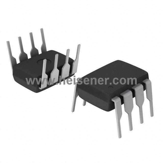
KA7500B Package
The KA7500B is available in a 16-DIP package. The package has 16 pins arranged in two rows for easy mounting on circuit boards.The 16-DIP package is moderately sized for a wide range of electronic devices and provides good heat dissipation. This design makes the KA7500B easy to assemble and maintain, and is widely used in switching power supplies and other power control systems.

FAQs
What is the primary function of the KA7500B?
The KA7500B is a pulse-width modulation (PWM) controller primarily used in switching power supplies and DC-DC converters to regulate output voltage and enhance power efficiency.
How does the KA7500B ensure overcurrent protection?
The KA7500B includes internal circuitry that monitors the output current and disables the output if the current exceeds a specified threshold, protecting the circuit from damage.
Can the KA7500B be used for both step-up and step-down conversion?
Yes, the KA7500B can be configured for both step-up (boost) and step-down (buck) conversion applications, depending on the external components used in the circuit.